

Quick start
The shortest route is the Wizard (Tools → New Design Wizard, Ctrl+Shift+N): choose what you want to do, enter the gear ratio or tooth count; the program opens with a suggestion that has passed its own checks. If you would rather start by hand, it takes six steps:
- Choose the manufacturing method. First line of the right panel: machining (hobbing / shaping), module cutter + dividing head, wire EDM / laser or 3D printing. The suggestions change with the method.
- Choose the gear type. From the cards on the left: single gear, pair (including double helical and crossed helical), rack, internal gear, worm gear, planetary set (spur or helical), bevel pair (straight or helical).
- Enter the module and tooth counts. The Gear section of the right panel. Sections are chosen from the strip on the left of the panel (Gear, Shift, Tolerance…); hovering over a button shows that section's summary. The result lights at the top of the panel show fitness for production and the safety factors; clicking a light opens the place concerned. In pairs the pinion can have a different width from the gear: Pinion width b₁ (e.g. gear 50 mm, pinion 70 mm; if left empty it equals b). Both gears sit on the same mid-plane, and strength is calculated with the width of the narrower one.
- Look at the result summary. Below the preview: a red line is a production blocker, yellow a warning, blue a suggestion.
- Press Fix if needed. A suggestion that has passed the program's checks is applied; review the result, Ctrl+Z undoes it.
- Get the output. Shop Card for the machine, DXF for CAM / laser, STL for 3D printing, STEP for CAD.
You model the gear's body (hub, recess, holes, keyway) in the 3D Design window. For ready examples, File → Example Projects (workshop, machinery, 3D printing). F1 shows the description of the field the cursor is in.
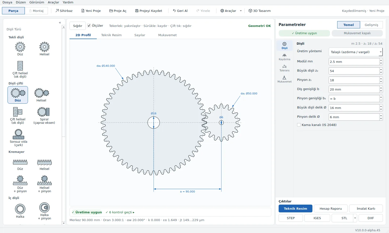
Three sample jobs (for the beta)
Three short jobs to get to know the program. Each ends with a check; if you send us the result with Help → Feedback, it helps us a lot.
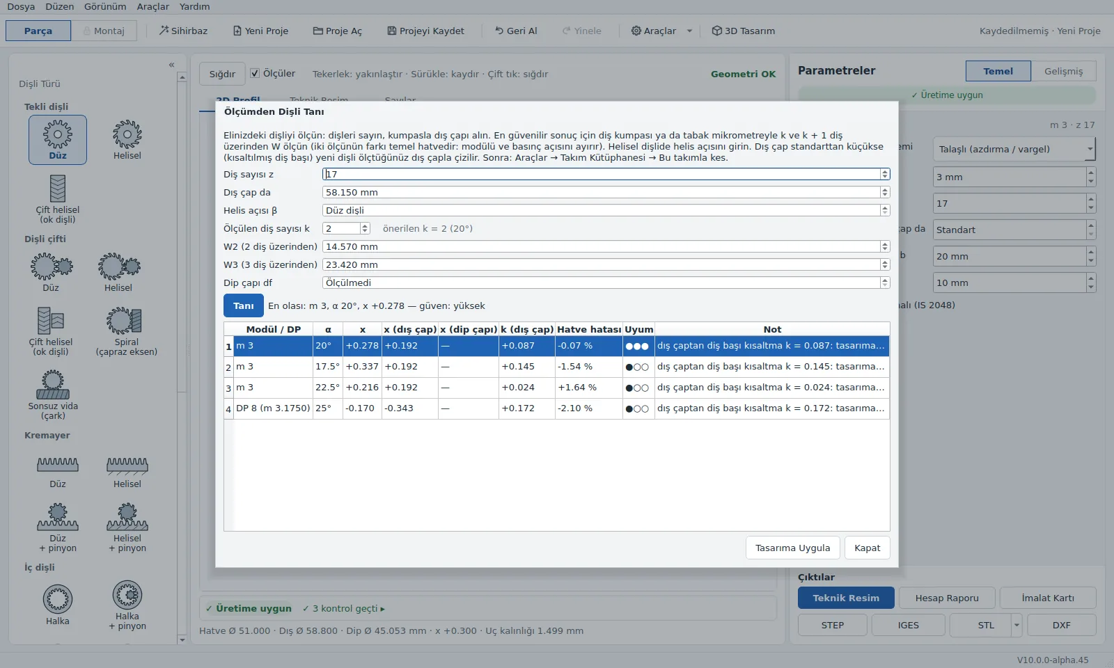
- Workshop: a new gear for a broken one. Wizard → Identify the gear I have: enter the tooth count, the tip diameter measured with a caliper and, if you know it, the span measurement; apply the most likely candidate. Choose the manufacturing method in the right panel (hobbing or module cutter + dividing head); if your tool is in the Tool Library, Cut with this tool. In 3D Design add a Hole (bore) and Keyway at the centre, then Shop Card. Check: measure the Wk value on the card on the old gear over the same number of teeth; if there is a difference, let us know.
- 3D printing: a gear pair with a given ratio. Wizard → Pair to print on a 3D printer: choose the ratio (e.g. 3) and the printer type, Start with this design. In 3D Design add a Hole (bore) at the centre of both gears, then STL. Check: print both gears, fit them on shafts and turn them by hand: there should be no binding or excess play.
- Machinery: a pair at a given centre distance, with strength. Wizard → Gear pair for a ratio: enter the ratio and centre distance. On the Strength tab tick the Strength calculation box and enter the torque (or power), speed and materials; look at the result lights, and if any is red, Fix. Then Drawing and STEP. Check: is the centre distance the value you wanted, are the safety factors (SF, SH) at the level you expected?
First launch
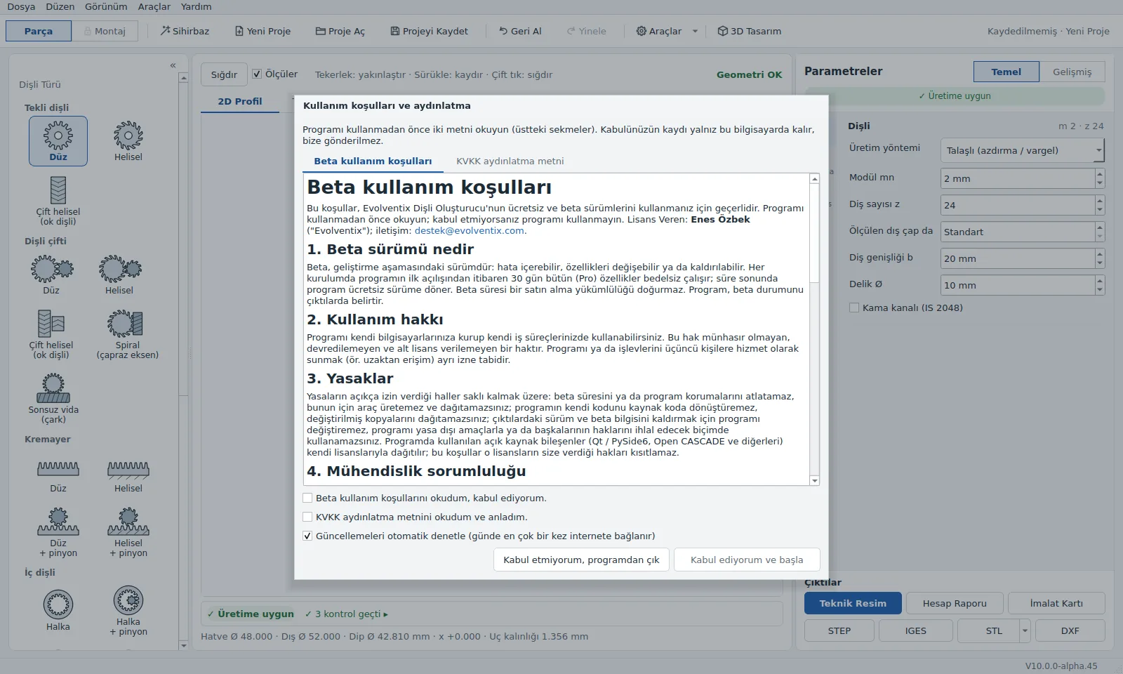
When the program opens for the first time the Privacy and beta terms window appears. It has two tabs: short beta terms of use and the KVKK privacy notice. To continue you must tick both “I have read and accept” boxes; if you choose I do not accept, quit the program, the program closes without doing anything else.
The same window has a Check for updates automatically box (it connects to the internet at most once a day). You can change your choice later and read the texts again at any time with Help → Privacy and KVKK….
During the beta, on every installation all features except Strength are unlocked for 30 days from first launch (Strength is unlocked for selected users with a key); no license key or machine code is asked for.
Screen layout
- Tabs: 2D Profile, Drawing, Numbers and Strength. On the drawing, zoom with the wheel, pan by dragging, double-click to see the whole sheet. Assembly is under development and closed for now.
- 3D Design window (the 3D Design button on the toolbar or Ctrl+3): the 3D model and the gear's body are drawn in a separate window; details below, in the 3D Design section.
- Basic / Advanced: from the View menu or the top of the right panel. Basic has the fields the workshop needs (module, tooth count, width, bore, profile shift, quality); Advanced has every input. Hidden fields keep their values.
- Find field: Ctrl+F finds a field by name and opens it.
- My starting values: from the File menu, you save values you use often as the start of new designs; you can return to factory values at any time.
- Reset layout: in the View menu; type panel open, result summary visible, Basic view.
- Comparison: Edit → Keep for Comparison, then Compare: two designs side by side, differences in yellow.
- Undo / redo: Ctrl+Z / Ctrl+Y; the changed fields are highlighted for a moment.
Result summary: Show and Fix
Below the preview the program states the design's status: fit for production, warning or production blocker. Passed checks are collected on one line; each problem has its reason next to it. Show finds and highlights the field concerned. Fix applies a correction that has passed the program's checks: for undercut, a thin tooth tip, low contact ratio, a thin rim between bore and root, backlash, interference or input errors.
“Fit for production” means the design has passed the program's geometry and production checks; it is not a guarantee. Material, load, heat treatment and the manufacturing decision are yours.

Broken or old gear
If the gear you have has no drawing: count the teeth and measure the tip diameter with a caliper. Then:
- Tools → Identify Gear from Measurements (broken / old gear) lists likely candidates for module (or diametral pitch), pressure angle and profile shift. The candidate you pick is applied to the design with one click; compare the result with the old part.
- If the measured tip diameter is smaller than standard, the program also estimates the tip shortening (k). On a single gear, the Measured tip diameter field in the Gear section does the same by hand.
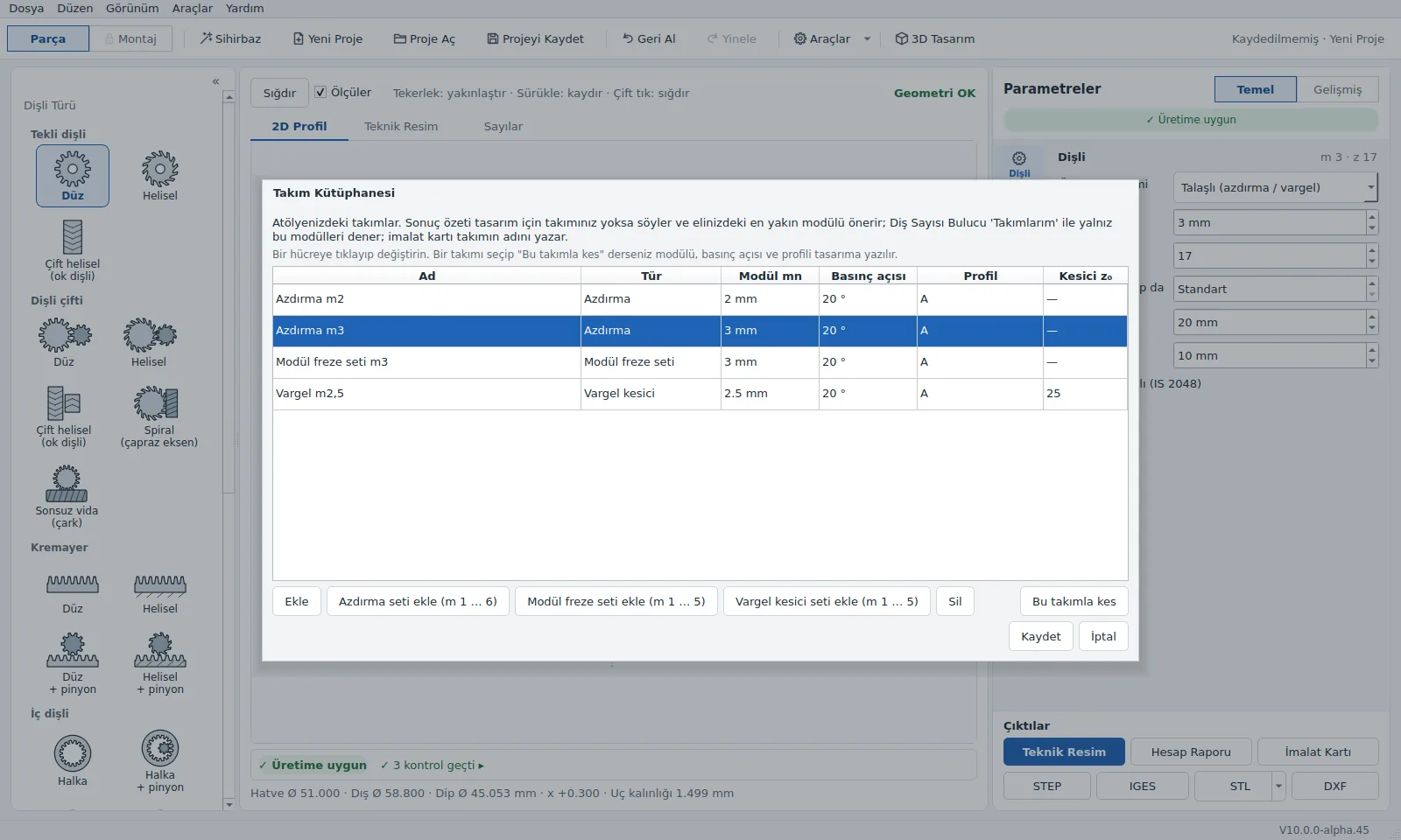
- In Tools → Tool Library, pick the tool in your workshop and click Cut with this tool: the tool's module, pressure angle and profile are written into the design.
Planetary gear set
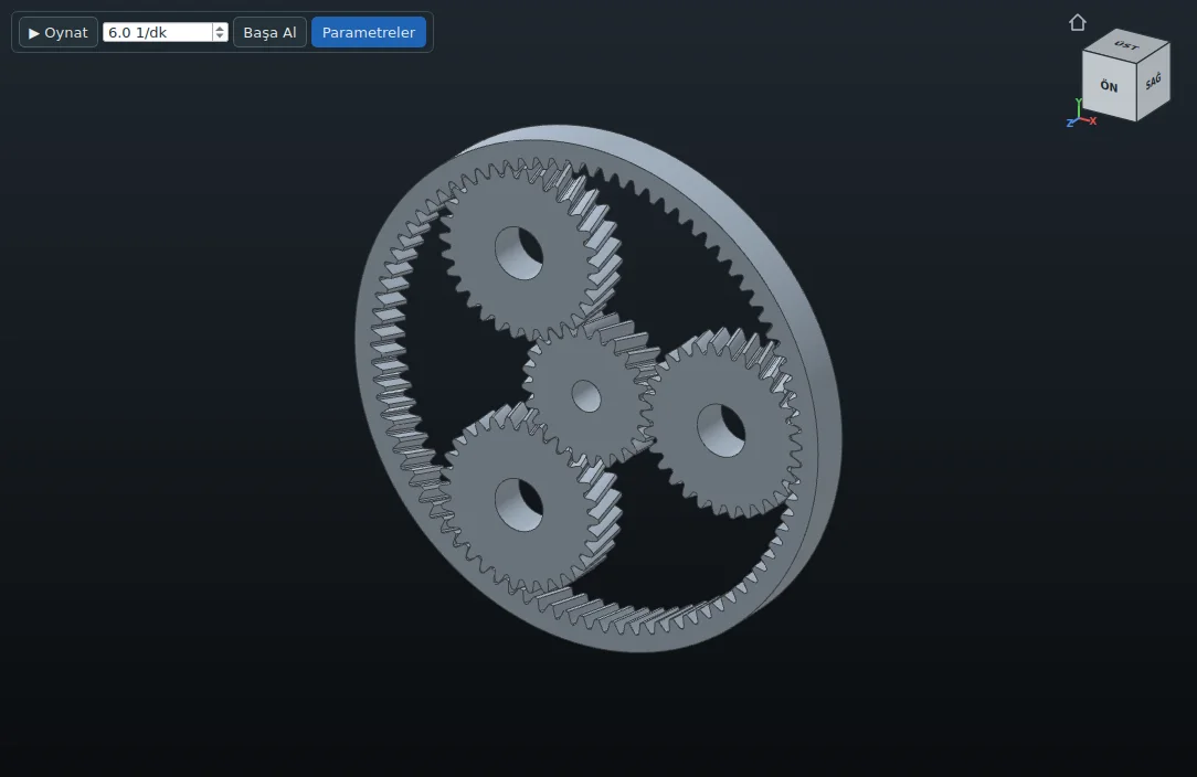
Planetary gear on the type cards: spur or helical. In the middle is the sun, around it the equally spaced planets, outside the ring (internal gear). In the Gear section you enter the sun, planet and ring tooth counts, the number of planets N and the bores; at first launch it comes with 24 / 30 / 84 teeth and three planets. The ring is usually zring = zsun + 2·zplanet. For the planets to be equally spaced, (zsun + zring) / N must be a whole number; if not, the program finds the nearest angles and warns you. If neighbouring planets touch, a production blocker appears.
You choose the Fixed member and Input member (most common: ring fixed, sun in, carrier out; i = 1 + zring / zsun). From the input speed and torque, the speeds and torques of all members and the torque carried by one planet are shown in the Numbers tab and the report; the ratio appears in the status line. The ring's profile shift is calculated from those of the sun and planet. Backlash jt in the Tolerance section is the backlash in each mesh; each part is thinned by half of it.
In the 3D view, pressing Play turns the planets with the carrier while the fixed member stays still. On the drawing, the Sheet list offers the assembly drawing or part drawings of the Sun, Planet and Ring. STEP / IGES / STL write separate files for the sun, one planet and the ring; DXF draws the whole set with layers.
Strength: the Strength tab also opens for the planetary set. The sun–planet and planet–ring meshes are each evaluated with ISO 6336. The torque carried by one planet is Tsun·Kγ / N. The load sharing factor Kγ comes from a typical table by number of planets; it is not taken from the standard, and you can enter your own value in the Load sharing Kγ field. Because planet teeth bend in both directions, YM = 0.7 is used for root safety; the ring's root is calculated like a rack tooth. As with a single gear, the result is a preliminary calculation. Tooth thickness allowances and adding to the assembly are the next step.
Bevel gear pair (straight and helical)
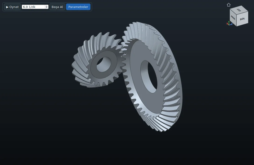
Bevel gear on the type cards: a bevel pair transmitting motion between two intersecting shafts, with straight or helical teeth (Gleason system). In the Gear section you enter the outer module (the module of the teeth at the back, i.e. the outer end), pinion and wheel tooth counts, Shaft angle Σ (10° … 170°, usually 90°), face width and bores; at first launch it comes with 20 / 40 teeth, 90°. The cone angles are calculated from the tooth count ratio so that δ₁ + δ₂ = Σ. The face width should not exceed a third of the outer cone distance or 10·m; if it does a warning appears, and beyond half a production blocker.
With x automatic on, the addenda come from the Gleason table (long pinion, short wheel addendum: x₂ = −x₁); if you turn it off, you enter x₁ by hand. Backlash jt (at the back) in the Tolerance section is the circumferential backlash at the back; both gears are thinned by half each. The status line shows the ratio, cone angles, outer cone distance Re, outside diameters and contact ratio.
The preview shows the section in the plane of the two axes; in the 3D view, pressing Play turns both gears on their own axes. On the drawing, the Sheet list offers the assembly section or part drawings of the Wheel and Pinion: outside diameter, bore, mounting distance (from cone apex to back face), face width and data table. For cutting with a module cutter, the shop card chooses the cutter from the virtual tooth count and says to tilt the dividing head by the root angle. STEP / IGES / STL write separate files for the wheel and pinion, DXF draws the section with layers. Load capacity (ISO 10300) and tooth thickness allowances are the next step.
In a helical bevel (spiral bevel) pair the teeth are curved; the pair runs smoother and quieter. In the Gear section you also enter the Mean spiral angle βm (35° at first launch, at most 45°), the pinion's Hand of spiral (the wheel has the opposite hand) and the Cutter radius rc; if rc is left at 0, the standard cutter closest to the mean cone distance is chosen. Here the face width should not exceed 0.3 times the outer cone distance or 10·m. The status line and report also show the overlap ratio εβ; below 1.25 a warning appears (Gleason recommends 1.5 … 2). The report, drawing table and shop card give the spiral angle, hand and cutter radius. Curved teeth cannot be cut with a module cutter on a dividing head: the shop card suggests a spiral bevel gear machine or 5-axis milling from the STEP model. Ready example: File → Example Projects → Helical bevel angle drive.
Roller chain sprocket
Chain sprocket on the type cards: the sprocket of an ISO 606 roller chain. In the Gear section you enter the chain (A series = ANSI 25 … 240, B series = European 05B … 48B), the number of strands (1–3), the number of teeth, the tip diameter (0: automatic to ISO 606) and the bore; at first launch it comes with an 08B chain and 17 teeth. The face width and the module come from the chain; involute gear fields such as module, pressure angle, profile shift and tooth thickness allowances are hidden. Tooth gap form in the Profile section picks the middle of the ISO 606 limits of ri, re and α, the minimum or the maximum gap.
Chain drive: enter Other sprocket z₂ and the number of links (rounded up to even), the centre distance and the wrap angle are calculated. Type the centre distance you want: if it does not fit exactly, Centre suggestion lists the nearest options (one even link count below / above, an odd count with an offset link, the other sprocket a few teeth more or less); go on with the one you pick using Apply suggestion. With Power P, Speed n and Service factor Ks the note shows, line by line, the power the chain carries, the static safety, the chain speed and the suggested lubrication. Suggest a chain for the power lists the chains that carry this power with the strands each needs; pick one and press Apply the chain picked.
With Show the chain links on, the chain appears in the preview with its ISO 606 links (inner and outer plates, rollers, bushes, pins) and goes into the STEP / IGES / STL output as a part of its own. With another sprocket entered, the closed chain wraps both sprockets, and pressing Play in the 3D view turns both sprockets the same way while the chain runs on. ISO 606 gives no plate thickness, so typical catalogue values are used. The drawing gives the chain table (measurement over rollers MR, tooth form, number of links); the report and the shop card give the ISO 606 dimensions. Ready example: File → Example Projects → Conveyor chain sprocket. The site has a roller chain sprocket calculator too.
3D Design
The gear's body (hub, rim, recess, holes, keyway, grooves) is drawn in the 3D Design window: the 3D Design button on the toolbar or Ctrl+3. The window is separate; it can be minimised, closed and reopened, and the main screen keeps working behind it. The tooth profile is edited on the main screen, the body shape only in this window. What you do to the body is carried into the project file, the drawing and the STEP / STL output.
Window layout
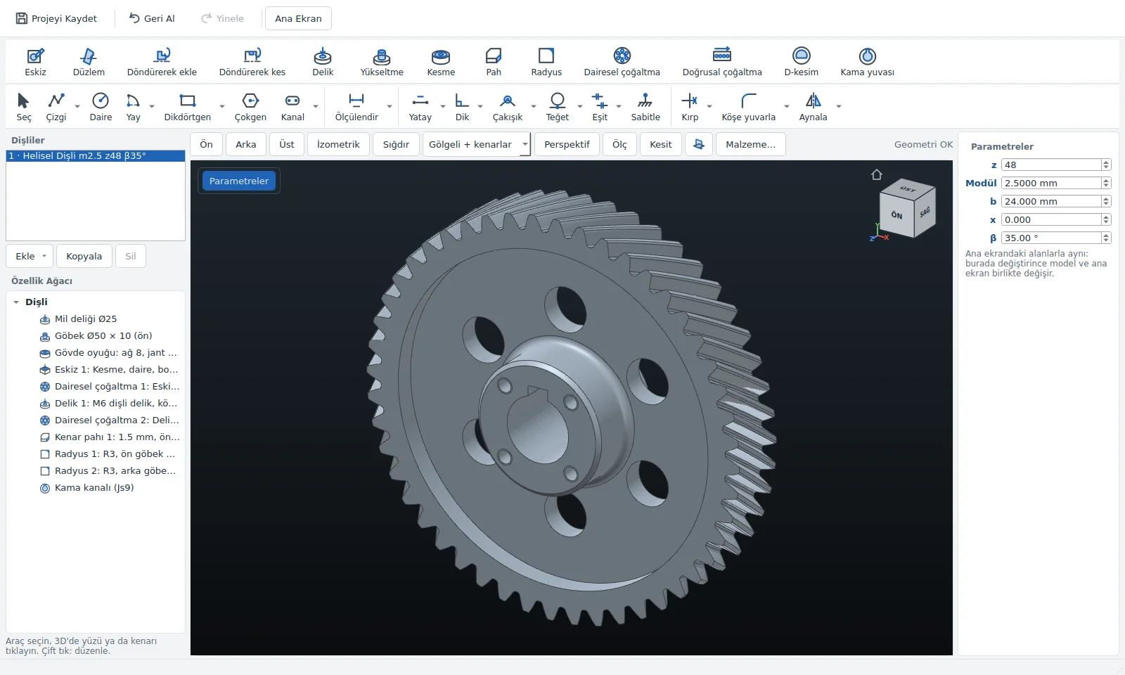
Feature tools at the top: Sketch (E), Revolve boss (Shift+B), Revolve cut (O), Hole (H), Boss (B), Cut (T), Chamfer (P), Fillet (Shift+R), Circular pattern (M), Linear pattern (Shift+M), D-cut (Shift+D), Keyway (W). On the left the gear list and the Feature Tree, in the middle the 3D view, on the right the Parameters panel: the design's main values (module, tooth count, width…) are here too and can be changed from here as well; the Parameters button at the top left of the 3D view hides or shows the panel. The Material… button opens the DIN material library: the material number and name are written in the title block and on the shop card, mass is calculated from the density, and the model's colour changes with the material.
Each feature (sketch, hole, chamfer…) is a separate row in the tree. Double-click to edit it; the right-click menu has Edit, Delete and Mirror to opposite face, which copies a sketch feature on one face to the gear's other face. A feature that cannot be built (a boss beyond the tip, a cut whose sketch is gone, a fillet that does not fit the corner …) does not take the body with it: the body stays with the other features, that feature appears in place in 3D as a dashed red line, the reason is written below the view, and in the tree it turns red with ⚠ (hover to see the reason). Outputs cannot be made until it is fixed. Drawing a sketch or hole turns the view normal to the face; once the sketch is confirmed and you move on to the Cut / Boss step, and the operation finishes and closes with ✓ or ✕, the view returns to the angle, zoom and position it had before (if the previous view was normal to the face, an oblique view opens for the operation step). Use Add in the Gears list to add gears of other types (e.g. a helical while working with a spur gear); selecting a gear in the list switches the main screen to it too, what is done to each gear stays with it, and the project file keeps them all.
Navigation and view
The wheel zooms towards the cursor; dragging rotates the view around the point you clicked. Clicking a face of the view cube at the top right looks from that direction, clicking an edge or corner from an in-between direction (home button: starting view); right-click opens the view menu (Front, Back, Left, Right, Top, Bottom, Isometric, Normal to face, Fit). Shortcuts: Ctrl+1 … Ctrl+7 standard views, Ctrl+8 normal to the selected face, F fit. Settings → View → 3D mouse layout: Classic (left button rotates) or CAD (middle button rotates, Ctrl+middle pans, Shift+middle zooms, left button selects).
The display style is chosen from the list above the view: Shaded + edges, Shaded, Semi-transparent (inside visible), Wireframe; the Perspective button shows near parts larger. Play turns the gears in mesh, Rewind returns them to the start position. The 3D view also shows the counterbores and countersinks of bolt holes, the thread circle of tapped holes, set screw and radial holes, and the shaft end chamfer.
Sketch: cut and boss
Experimental tools: Sketch, Plane, Linear pattern and Suppress are still being developed; when opened, a yellow note at the top of the panel reminds you of this. Check the result in 3D and on the drawing; you can send your views with Help → Feedback. The body's own tools (hub, bore, keyway, D-cut, hole, revolve, chamfer, fillet, circular pattern) are not in this group.
In the Sketch tool you first click a face or plane. The Planes button (Shift+E) shows or hides the Front, Top and Right planes in 3D; clicking one opens the sketch on that plane. If you press a drawing key (e.g. C circle, R rectangle) while no sketch is open, the program waits for you to pick a face, and the sketch opens with that tool on the face you click. N looks normal to the sketch plane. The Plane offset box shifts the plane: the Right and Top planes open this far from the axis, the front / back face and a face chosen from the list this far from the face (a negative value goes into the face); the planes in 3D move too. The offset can also be changed later from the sketch panel.
The Plane tool builds a plane with its own row in the tree: the Right or Top plane is rotated by an angle about the axis and / or shifted a distance from the axis (e.g. for a radial hole or groove at 30°). An optional name can be given. In the Sketch tool, clicking the plane's button or the plane in 3D opens the sketch on that plane; you can also right-click the plane in the tree and choose Sketch on this plane. When the plane's angle or offset is changed later, the sketches on it follow; if the plane is deleted, the sketches on it are deleted too.
To try without a feature without deleting it, right-click it in the tree and choose Suppress (experimental): the row turns grey and "(suppressed)", its values stay; the 3D model, drawing and outputs are made as if the feature were not there. Sketches resting on it are suppressed with it. Unsuppress brings it back (if the feature it depends on is suppressed, that is unsuppressed too).
- Drawing: S select, L line, Shift+L centreline, C circle, R rectangle (corner, centre, three-corner, parallelogram), K slot, Y arc, U three-point arc, G tangent arc, V turn edge into arc; polygon (regular, 3–40 sides) and slot types are in the tool list. Shift+Y makes the selected shape construction geometry: it does not take part in the cut, but takes dimensions and relations.
- Editing: Z trim, I extend, J sketch fillet, Shift+J sketch chamfer, Shift+A mirror, Shift+O offset.
- Dimension: D dimension, A angle, X radius. When a dimension value is typed, the shape follows it.
- Relations: 1 horizontal, 2 vertical, 3 perpendicular, 4 parallel, 5 collinear, 6 equal, 7 coincident, 8 tangent, 9 concentric, 0 midpoint, Shift+S symmetric, Shift+F fixed.
- Snapping: corners, centres, the four quadrant points of a circle and the corners and edges of earlier sketches are named; dimensions and relations attach to them too.
In closed shapes drawn one inside another, the inner shape becomes a hole. ✓ Finish (Enter) closes the sketch and the shapes go into the model as a Cut or Boss. In the sketch you choose the End condition: blind (depth, from the face the shape sits on), through all, up to next (until it leaves the material below the shape), up to face (up to the plane of the chosen face) or mid-plane (both ways); the Show in 3D button switches to the 3D view, where the depth is changed by dragging the arrow tip (Shift: fine steps). On an offset plane, blind depth and boss length are measured from that plane; Reverse direction turns the boss towards the body (backwards from a plane in front), and on the Right / Top plane turns a blind end the other way. A cut that does not reach the part or a boss that does not touch the body is rejected with the reason. A shape that cannot be made is rejected with the reason: if there is no closed shape, if a polygon's edges cross, or if in a through cut the inner shape would be left as a separate piece (an island).
Revolve, hole, chamfer, fillet and pattern
- Revolve cut and Revolve boss open the section through the axis (axis horizontal, up is radius): the closed shape you draw turns a full revolution about the axis; a cut opens a groove in the hub or shaft, a boss adds a collar. The operation can also be changed later from the panel.
- Hole: the point you click on the face becomes the hole's first point and a drawing opens on the face: holes appear as circles at drill diameter, Hole point (Shift+H) adds a new hole. Give the position with Dimension and relations (distance to the centre, the hub or another hole; construction lines and circles can be drawn too); a dimension to the hub or an earlier hole moves the hole when that changes. Choose the Face (front / back) in the panel. A hole that cannot be made (running into the teeth, too deep, touching another hole …) appears in place in 3D as a dashed red line with the reason below; outputs cannot be made until it is fixed. Types: plain hole (diameter), clearance hole (M3–M24, ISO 273 close / normal / loose), tapped hole (tap drill, thread length), counterbore and 90° countersink (dimensions from the table or by hand); end condition through all or blind (depth is the full-diameter length, with a 118° drill point below). On the drawing a hole callout (e.g. 4× M6 ↧9 / Ø5 ↧12) and a Holes row in the table appear.
- Radial hole: clicking the side face of the hub or shaft with the Hole tool opens the hole towards the axis. The types are as for an axial hole; the end condition is Up to bore, Through all or Blind. The position is given by two values: Angle (from top) (counter-clockwise looking at the face from the front) and the distance of the hole axis from the chosen face (Side: front / back). A new click on the same side face adds a point; with several points, choose from the Point list. A circular pattern can be used, a linear one cannot. For a set screw position choose a tapped hole and Up to bore. A radial hole running into the teeth or past the end of the hub, larger than the bore or touching another hole is rejected with the reason. On the drawing it appears in the section and the callout, and in the Holes table.
- Chamfer and Fillet: first type the size, then pick a circular edge (hub base or end, recess floor corner, rim edge, hole mouth, shaft step). A fillet rounds an outside edge and adds material to an inside corner; the tip edge cannot be filleted. Chamfer puts an edge chamfer on the same edges one by one (tip, hole mouth and shaft end chamfers on both faces together).
- Circular pattern repeats a hole or sketch shape about the axis: count, total angle (360° full turn; if smaller, the copies spread over that angle) and copies to skip (ticked in the list, or click the copy in 3D while the panel is open). The pattern is a separate feature in the tree; when deleted, the sketch or hole is left on its own.
- Linear pattern repeats a hole or sketch shape along a line at equal spacing: count, spacing (mm) and direction (0° right, 90° up, looking at the face from the front); copies to skip are chosen as in the circular pattern. It is also used on racks. A feature has either a circular or a linear pattern: one replaces the other.
- D-cut makes a flat in the bore to sit on the shaft flat, Keyway cuts a keyway in the bore.
Measure, section and mass
With the Measure button on, clicking a face, edge or hole shows its diameter, length and position; a second click measures between the two (axial distance between faces, radial distance between diameters, between hole axes, angle about the axis, wall thickness, between points); a third click starts a new measurement, Esc clears, Esc again closes. The Section button cuts the model with a plane: choose the plane (top and right planes pass through the axis, the front plane is normal to the axis), move it with the slider, Reverse direction shows the other side; cut faces appear hatched (needs OpenGL). Mass and moment of inertia are calculated from the 3D model with the density of the chosen material and written in the report.
Measurement Check and Record
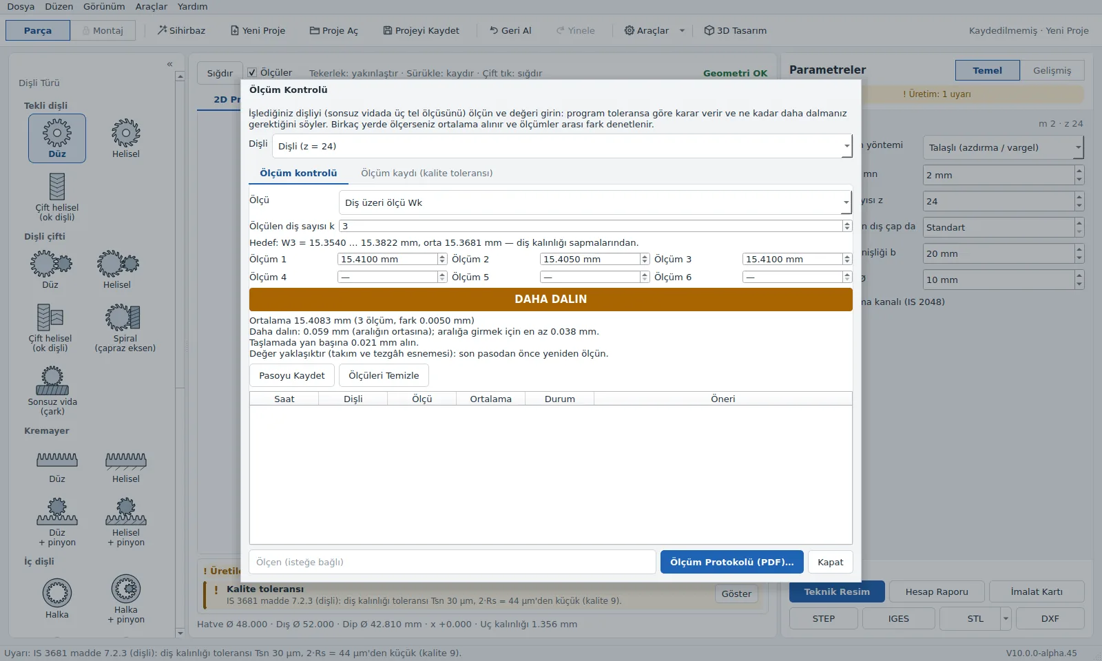
Tools → Finish Check compares the span measurement (Wk) or dimension over balls (MdK) of the gear you are machining with the tolerance and shows roughly how much deeper to cut. For a worm it gives the three-wire dimension M3, the best wire diameter and (if you entered an allowance) the acceptance range; the same lines appear in the Report, the Numbers tab and the Shop Card.
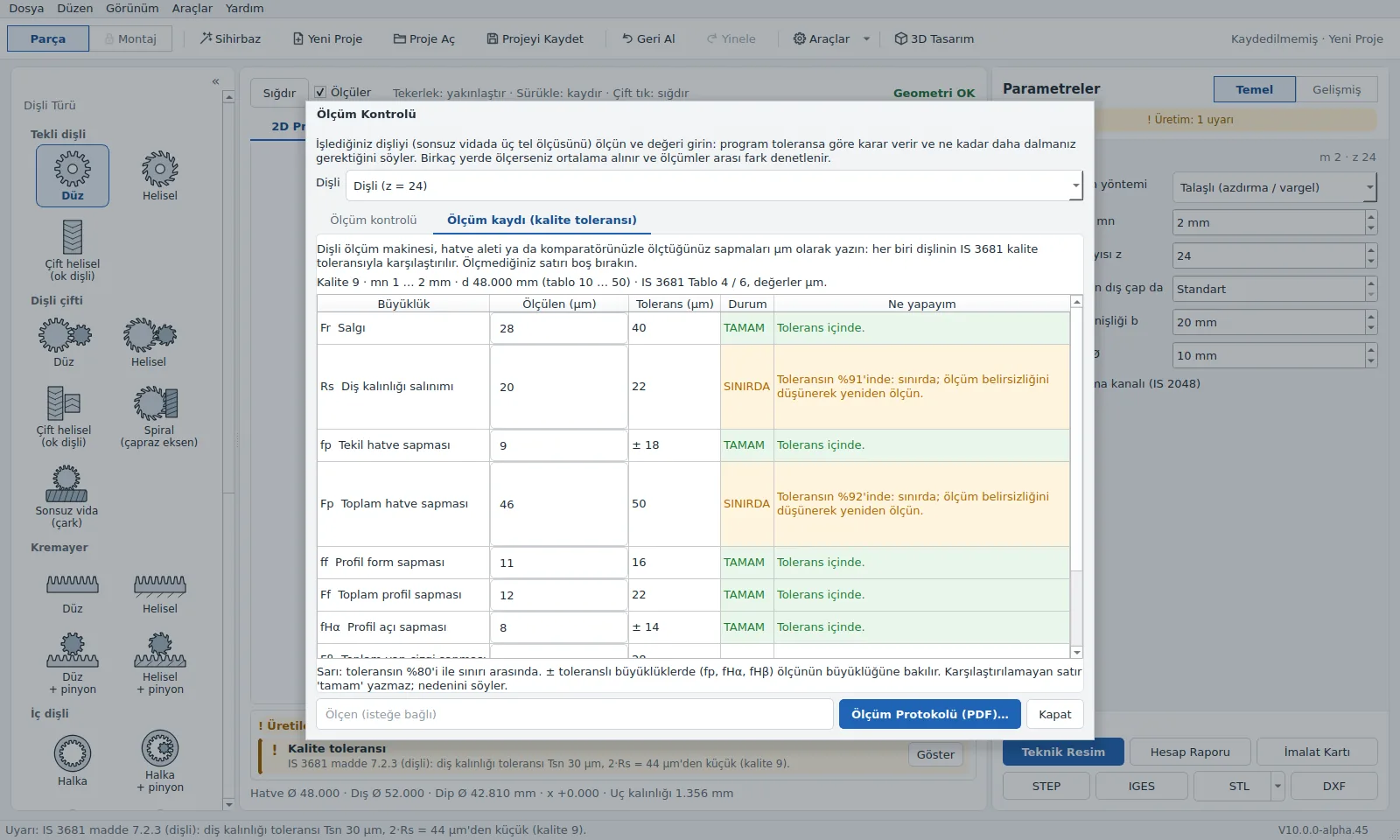
Tools → Measurement Record… compares the runout, pitch, profile and helix deviations you measured with the gear's IS 3681 quality tolerance and shows which quality it stays within.
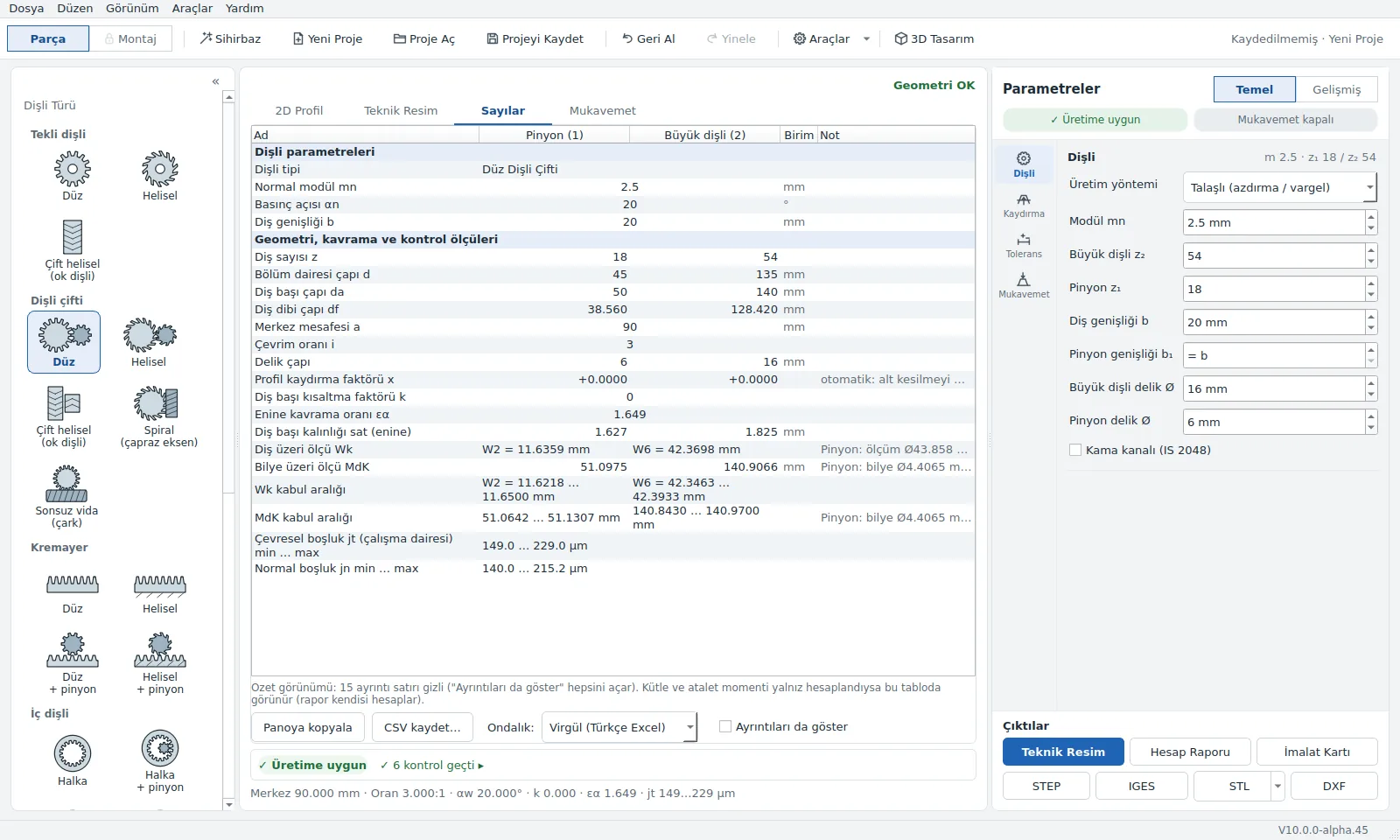
Numbers tab
Opened with Ctrl+5. It shows the main figures of the calculation (diameters, measurement targets, ratios, results) as name, value and unit in Pinion | Gear columns. A value's explanation is not mixed into the value: it is in the grey Note column. A value common to both (such as the centre distance) sits between the two columns.
Ticking Show details also lists intermediate values, the tolerance table and factors; when the box is not ticked, the number of hidden detail rows is shown below the table. On screen numbers appear with at most three decimals, while copying and CSV take the report's full digits. Copy to clipboard takes the on-screen table in a form you can paste into Excel; Save CSV… writes a file; the decimal separator is selectable. In the free edition only the numbers visible in that edition are listed.
Preliminary strength calculation
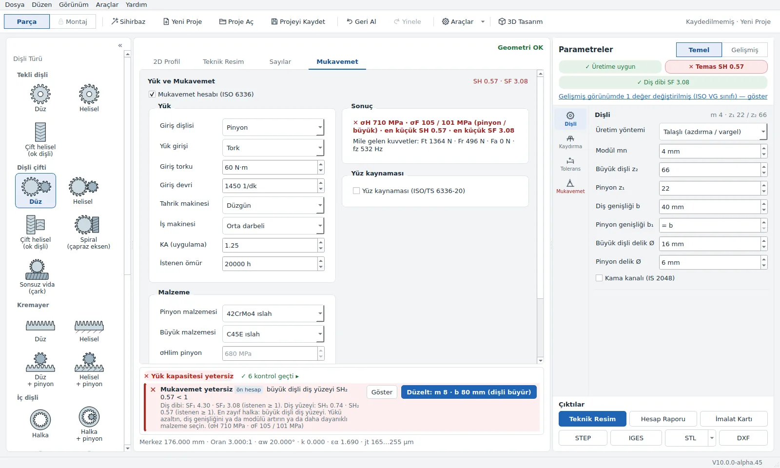
Open the Strength tab in the middle (Ctrl+6 or the Strength button on the right panel's strip) and tick the Strength calculation (ISO 6336) box. The inputs are on cards (Load, Material, Load factors, Oil and surface, Scuffing), with the result beside them. Enter the input torque (or power) and speed, the shock conditions of the driver and driven machine (KA is chosen from this) and the material of both gears; if you do not know the load factors, leave them empty and the program calculates them (below). The material list has ISO 6336-5 types beside the textbook materials (normalised, through-hardened, cast, case-hardened, induction-hardened, nitrided…): for those you choose the material quality (ML, MQ, ME) and the surface hardness of each gear, and σHlim and σFlim come from ISO 6336-5:2016 Table 1. For a hardened gear the report also gives the suggested case depth.
The result summary shows the root and flank safety factors (SF and SH). The result carries a preliminary badge and the assumptions used are shown: this is not the full ISO 6336 method. If the dynamic factor and load distribution factors (KV, KHβ, KHα) are not entered, they are calculated with ISO 6336-1:2019 from the gear quality, speed and the pinion's bearing arrangement. Flank safety is calculated per ISO 6336-2:2019 with the required life (hours; unlimited can also be chosen), the oil's ISO VG grade and the flank roughness (from the table on the drawing); for a helical pair, flank modification can also be chosen. The same tab has the forces (Ft, Fr, Fa), the tooth mesh frequency (fz) and scuffing. In a planetary set sun–planet and planet–ring are calculated separately (Planetary gear set). The Strength tab belongs to the Strength module; during the beta it is open only to selected users, and on other installations the tab stays in place but is locked (it says on it how to unlock it).
Outputs
| Output | What for |
|---|---|
| Shop Card (one page) | Machine: tool, turning diameter, infeed depth, Wk / MdK acceptance ranges, cutter number, dividing head |
| Drawing sheet | Dimensioned drawing and table; paper and scale are adjustable, add your own dimensions with Smart dimension |
| PDF report | Inputs, results and checks (Calculation and production module) |
| DXF | CAM, laser, wire EDM |
| STL | 3D printing (with teeth thinned by the print clearance) |
| STEP, IGES | CAD (free for spur gears; for other types, that gear's module). For pairs, the assembly in one file, each part in a separate file (on its own axis, at the origin) or both |
Your own dimension on the drawing: on the Drawing tab press the Smart dimension button, then click the item to measure: it gives an edge's length, a circle's diameter, an arc's radius; a second item gives the distance between them or the angle between two edges. With the mouse above or below it is horizontal, to the side vertical, diagonally aligned; right-click locks the type, Shift takes a circle's edge instead of its centre, Esc cancels. Dimensions are tied to the part: they are redrawn when a value changes; if the place they measure no longer exists they turn red. To delete, click the dimension text (Ctrl + click adds one more, Ctrl+A all), then Delete. The Top view box adds a top view below the front view on a single-part drawing. Smart dimension works on single gears and pair part drawings, and on planetary and bevel sheets; it is not yet available on the assembly drawing or on rack, internal gear and worm sheets.
Shortcuts: Ctrl+P and Ctrl+Shift+P, Ctrl+M, Ctrl+E, Ctrl+D; full list in Help → Keyboard Shortcuts (Ctrl+F1).
Settings and shortcuts
Tools → Settings (Ctrl+,): startup behaviour (wizard, empty project or last project), company details (written in the title block of every new project), auto recovery, project and output folders, drawing defaults, STL format, font size, theme (classic grey, light, dark), shortcuts and performance options. Settings can be exported to a file and taken to another computer.
| Shortcut | Action |
|---|---|
| Ctrl+Shift+N | New Design Wizard |
| Ctrl+F | Find field |
| Ctrl+3 | 3D Design window |
| Ctrl+5 | Numbers tab |
| Ctrl+6 | Strength tab |
| Ctrl+Z / Ctrl+Y | Undo / redo |
| F1 | Description of the field the cursor is in |
| Ctrl+, | Settings |
| Ctrl+F1 | Keyboard shortcut list |
The keys of the 3D Design window and the sketch (E sketch, H hole, Shift+E planes, 1 … 0 relations…) are in the 3D Design section. All are listed in Help → Keyboard Shortcuts and can be changed in Settings → Shortcuts.
Privacy and updates
The program sends no usage data (telemetry); your project files and settings stay only on your computer. For feedback and bug reports the program itself sends nothing: Help → Feedback opens your own email program and you send it.
If the update check is on, it connects to the download site at most once a day to read the version information; the server sees your IP address while doing so. You can turn it off with Help → Check for updates automatically or in Settings. A downloaded installer is not run until its signature and SHA-256 value are verified.
If you have a question or have found a bug, use Help → Feedback or write to us: destek@evolventix.com
Guides