

Gear calculator
Calculate the diameters, tooth thickness and span measurement of a spur gear below; the gear's technical drawing and 3D view are drawn with the values. There are separate pages for gear pairs, helical, internal gears, rack, worm, bevel and planetary gears.
Spur gear calculator
Parameters
Face width and bore are only for the drawing; they do not change the calculation. ISO 53 Type A basic rack: addendum 1·m, dedendum 1.25·m, no tip shortening. The span tooth count k is the number for which the measuring contact lies on the usable involute, closest to the reference circle. Allowance and tolerance series are from the program's tables (based on IS 3681 = DIN 3967); the limits are measured with the same k and the same pin. Pin diameter D is chosen so that contact lies on the d + 2xm circle and rounded to 0.05 mm; with an odd tooth count M is measured across the two farthest opposite spaces.
Gear data · spur gear
- Reference diameter d
- mm
- Tip diameter da
- mm
- Root diameter df
- mm
- Base diameter db
- mm
- Tooth thickness s (on the reference circle)
- mm
- Tip thickness sa
- mm
- Span tooth count k
- Span measurement Wk
- Pin / ball diameter D
- Dimension over pins M
- Tooth thickness allowances Asne / Asni
- Wk limits max / min
- M limits max / min
- Undercut limit xmin
- Base pitch pb
- mm
Spur gear formulas
| Quantity | Formula | Example |
|---|---|---|
| Reference diameter | d = m · z | 48.000 mm |
| Tip (outside) diameter | da = m · (z + 2) | 52.000 mm |
| Root diameter | df = m · (z − 2.5) | 43.000 mm |
| Base diameter | db = d · cos 20° | 45.105 mm |
| Pitch | p = π · m | 6.283 mm |
| Tooth thickness | s = π · m / 2 | 3.142 mm |
| Tooth depth | h = 2.25 · m | 4.500 mm |
| Module from the tip diameter | m = da / (z + 2) | 2.000 mm |
| Dimension over pins | inv αM = inv α + D / db − π / z + s / d; M = db / cos αM + D (odd z: db cos(90°/z) / cos αM + D) | D automatic |
Video tip
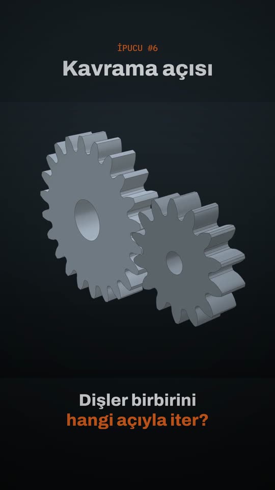
This calculator is for a single spur gear; the other types are in the "Gear calculators" list. You can download the technical drawing as DXF, SVG or PDF and the gear as STL from every calculator for free; profile-shifted pairs, strength and STEP output are in the program. Diameters and Wk are calculated with the formulas in the program's calculation core; how they are checked is written on the verification page. For a manual check see the span measurement guide.