

Internal gear calculator
Main dimensions of an internal (ring) gear and the pinion turning inside it. On an internal gear the teeth face inwards: the tip diameter is smaller than the reference circle, the root diameter larger.
Results · internal gear
- Internal gear reference diameter d₂
- 120.000 mm
- Internal gear tip diameter da2
- 116.000 mm
- Internal gear root diameter df2
- 125.000 mm
- Pinion reference diameter d₁
- 40.000 mm
- Pinion tip diameter da1
- 44.000 mm
- Pinion root diameter df1
- 35.000 mm
- Working centre distance a
- 40.000 mm
- Zero centre distance a₀
- — mm
- Working pressure angle αw
- — °
- Internal gear tip shortening k·m
- — mm
- Gear ratio i
- 3.000
- Pitch p
- 6.283 mm
- Tooth depth h
- 4.500 mm
- Contact ratio εα
- —
- Span measurement W (pinion)
- — mm
- Dimension over balls/pins M (pinion)
- — mm
- Dimension between balls M (internal gear)
- — mm
- Tooth thickness allowances Asne / Asni (pinion)
- — mm
- W limits max / min (pinion)
- — mm
- M limits max / min (pinion)
- — mm
- Tooth thickness allowances Asne / Asni (internal gear)
- — mm
- M limits max / min (internal gear)
- — mm
Results are for the initial values; they update when you change the values.
Internal gear formulas
| Quantity | Formula | Example |
|---|---|---|
| Reference diameter | d = m · z | 120.000 mm |
| Internal gear tip diameter | da2 = m · (z₂ − 2) | 116.000 mm |
| Internal gear root diameter | df2 = m · (z₂ + 2.5) | 125.000 mm |
| Pinion tip diameter | da1 = m · (z₁ + 2) | 44.000 mm |
| Centre distance | a₀ = m · (z₂ − z₁) / 2 | 40.000 mm |
| Working pressure angle | inv αw = inv α + 2(x₂ − x₁) tan α / (z₂ − z₁) | 20.000° (x = 0) |
| Working centre distance | a = a₀ · cos α / cos αw | 40.000 mm |
| Shifted diameters | da1 = d₁ + 2m(1 + x₁), da2 = d₂ − 2m(1 − x₂ − k), df2 = d₂ + 2m(1.25 + x₂) | 44.000 / 116.000 / 125.000 mm |
| Gear ratio | i = z₂ / z₁ | 3.000 |
| Dimension over balls/pins | inv αM = inv α + D / db − π / z + s / d; M = db / cos αM + D (odd z: db cos(90°/z) / cos αM + D) | D automatic: contact on the d + 2xm circle |
| Dimension between balls (internal gear) | inv αM = inv α + e / d − D / db; M = db / cos αM − D, e = m(π/2 + 2x tan α) | x > 0 opens the space |
| Measurement limits | W = W₀ + Asn · cos αn; M with the same ball for thickness s + Asn (Asne upper, Asni = Asne − Tsn lower allowance) | cd25 default |
What you should know
For an internal gear the centre distance is calculated from the difference of the tooth counts; for the same ratio it is much shorter than for an external pair. That is why the ring is used in planetary gears.
As the tooth count difference z₂ − z₁ gets smaller, the pinion's tip can catch on the internal gear's teeth (tip interference). The program checks for interference; this page only requires a difference of at least 4 teeth.
An internal gear is cut not with a rack-type tool but with a pinion-type shaper cutter; the root diameter may differ slightly depending on the cutter.
Video tip
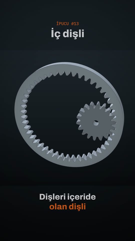
Design this gear with profile shift in the program; get undercut and interference checks, strength, technical drawing, 3D model and STEP / DXF output.
Apply for the free beta