

Worm gear calculator
Worm and wheel on shafts crossing at 90°. The module is the worm's axial module; the diameter quotient q is the ratio of the worm's reference diameter to the module.
Results · worm gear
- Gear ratio i
- 40.00
- Lead angle γ
- 5.711 °
- Worm reference diameter d₁
- 25.000 mm
- Worm tip diameter da1
- 30.000 mm
- Worm root diameter df1
- 19.000 mm
- Axial pitch px
- 7.854 mm
- Lead pz
- 7.854 mm
- Worm axial tooth thickness sx1
- — mm
- Worm normal tooth thickness sn1
- — mm
- Measuring wire diameter D
- — mm
- Dimension over three wires M
- — mm
- Wire contact diameter
- — mm
- Wheel reference diameter d₂
- 100.000 mm
- Wheel throat diameter da2
- 105.000 mm
- Wheel root diameter df2
- 94.000 mm
- Centre distance a
- 62.500 mm
- Centre distance without shift a₀
- — mm
- Efficiency (worm driving) η
- 64.9 %
- Is it self-locking?
- No
- Efficiency (wheel driving) η′
- 46.6 %
Results are for the initial values; they update when you change the values.
Worm gear formulas
| Quantity | Formula | Example |
|---|---|---|
| Gear ratio | i = z₂ / z₁ | 40.00 |
| Worm reference diameter | d₁ = q · m | 25.000 mm |
| Lead angle | tan γ = z₁ / q | 5.711 ° |
| Axial pitch | px = π · m | 7.854 mm |
| Lead | pz = z₁ · π · m | 7.854 mm |
| Wheel reference diameter | d₂ = z₂ · m | 100.000 mm |
| Wheel throat diameter | da2 = d₂ + 2 · m · (1 + x₂) | 105.000 mm |
| Worm root diameter | df1 = d₁ − 2.4 · m | 19.000 mm |
| Centre distance | a = (d₁ + d₂) / 2 + x₂ · m | 62.500 mm |
| Shifted wheel | da2 = d₂ + 2m(1 + x₂), df2 = d₂ − 2m(1.2 − x₂) | 105.000 / 94.000 mm |
| Efficiency | η = tan γ / tan(γ + ρ′), tan ρ′ = μ / cos αn, μ = 0.05 | 64.9 % |
| Dimension over three wires | D = (px / 2) / cos αx (suggested); the wire lies along the helix of the tooth space and touches the flanks with its centre at radius ρc: M = 2 (ρc + D / 2) | ZA worm, straight flank in the axial section |
| Worm tooth thickness | sx1 = px / 2, sn1 = sx1 · cos γ | on the reference cylinder |
What you should know
A single-start worm turns the wheel by one tooth per revolution; that is why large ratios such as 40:1 are reached in a single stage.
If the lead angle γ is smaller than the friction angle, the wheel cannot drive the worm: the drive is self-locking. This is wanted in hoists, but efficiency drops.
Efficiency is for a friction coefficient μ = 0.05 (lubricated, bronze wheel, steel worm). In the program you can change μ and also see the forces and sliding speed.
Video tip
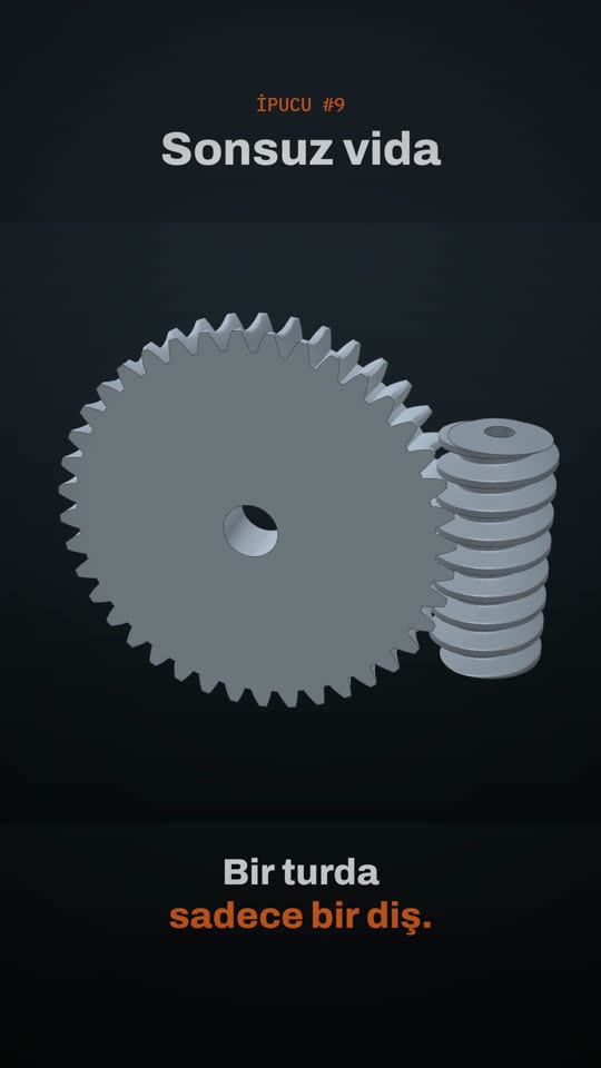
Design this gear with profile shift in the program; get undercut and interference checks, strength, technical drawing, 3D model and STEP / DXF output.
Apply for the free beta