

Gear pair calculator
Main dimensions of two spur gears driving each other. Enter the module, both tooth counts and, if you like, the profile shift; centre distance, diameters, span measurements and technical drawing are calculated at once.
Results · gear pair
- Working centre distance a
- 60.000 mm
- Zero centre distance a₀
- 60.000 mm
- Working pressure angle αw
- 20.000°
- Tip shortening k·m
- 0.000 mm
- Gear ratio i
- 2.000
- Reference diameter d₁
- 40.000 mm
- Reference diameter d₂
- 80.000 mm
- Tip diameter da1
- 44.000 mm
- Tip diameter da2
- 84.000 mm
- Root diameter df1
- 35.000 mm
- Root diameter df2
- 75.000 mm
- Base diameter db1
- 37.588 mm
- Base diameter db2
- 75.175 mm
- Span measurement W (pinion)
- 15.321 (k 3) mm
- Span measurement W (gear)
- 27.690 (k 5) mm
- Dimension over balls/pins M (pinion)
- — mm
- Dimension over balls/pins M (gear)
- — mm
- Tooth thickness allowances Asne / Asni (pinion)
- — mm
- W limits max / min (pinion)
- — mm
- M limits max / min (pinion)
- — mm
- Tooth thickness allowances Asne / Asni (gear)
- — mm
- W limits max / min (gear)
- — mm
- M limits max / min (gear)
- — mm
- Normal backlash jn min … max
- — mm
- Pitch p
- 6.283 mm
- Tooth depth h
- 4.500 mm
- Contact ratio εα
- 1.635
- Gear speed n₂
- 725.0 rpm
Results are for the initial values; they update when you change the values.
Gear pair formulas
| Quantity | Formula | Example |
|---|---|---|
| Gear ratio | i = z₂ / z₁ | 2.000 |
| Reference diameter | d = m · z | 40.000 mm |
| Tip diameter | da = m · (z + 2) | 44.000 mm |
| Root diameter | df = m · (z − 2.5) | 35.000 mm |
| Base diameter | db = d · cos 20° | 37.588 mm |
| Zero centre distance | a₀ = m · (z₁ + z₂) / 2 | 60.000 mm |
| Working pressure angle | inv αw = inv α + 2(x₁ + x₂) tan α / (z₁ + z₂) | 20.000° (x = 0) |
| Working centre distance | a = a₀ · cos α / cos αw | 60.000 mm |
| Tip shortening | k · m = a₀ + (x₁ + x₂) · m − a | 0.000 mm |
| Shifted tip diameter | da = d + 2m (1 + x − k) | 44.000 mm |
| Shifted root diameter | df = d − 2m (1.25 − x) | 35.000 mm |
| Pitch | p = π · m | 6.283 mm |
| Tooth depth | h = (2.25 − k) · m | 4.500 mm |
| Output speed | n₂ = n₁ · z₁ / z₂ | 725.0 rpm |
| Dimension over balls/pins | inv αM = inv α + D / db − π / z + s / d; M = db / cos αM + D (odd z: db cos(90°/z) / cos αM + D) | D automatic: contact on the d + 2xm circle |
| Measurement limits | W = W₀ + Asn · cos αn; M with the same ball for thickness s + Asn (Asne upper, Asni = Asne − Tsn lower allowance) | cd25 default |
| Normal backlash | jbn = jwt cos αwt cos βb, jwt = (cos αt / cos αwt) [pt − s₁ − s₂ + (d₁ + d₂)(inv αwt − inv αt)], a ± Aa | min: upper allowances, a − Aa |
What you should know
The centre distance a is the sum of the reference radii of the two gears. If you are choosing gears for an existing housing, measure a first; m · (z₁ + z₂) / 2 must match it. If it does not, profile shift is needed.
The contact ratio εα shows how many tooth pairs work at the same time. Below 1.2 means noisy, impact-prone running; for spur gears 1.4–1.8 is good.
On a pinion with fewer than 17 teeth the tooth root is cut away during cutting (undercut). The page warns about this; the cure is profile shift.
Video tip
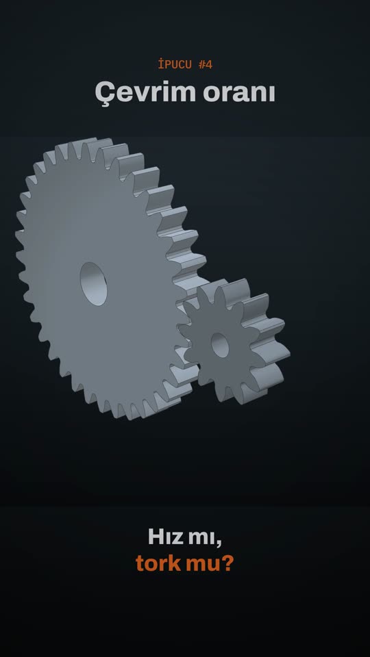

Design this gear with profile shift in the program; get undercut and interference checks, strength, technical drawing, 3D model and STEP / DXF output.
Apply for the free beta